Cylinder and carrier
Machine model, cylinder reference, inner diameter and thickness of the carrier, and usable working width are defined together. Inner and outer diameter information must not be confused.

ROTARY CUTTING / TECHNICAL GUIDE
Rotary cutting in corrugated board relies on the coordinated operation of the curved cutting die, cutting rule, sheet, and counter arrangement. Cutting die evaluation starts with accurate machine information.
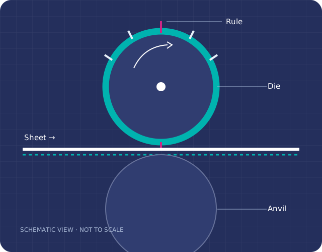
WHAT IS A ROTARY CUTTING DIE?
In a rotary cutting die, the cutting rules are positioned on a curved carrier. The carrier is mounted to the die cylinder of the machine; cutting takes place as the sheet passes between the cylinders.
Unlike flatbed cutting, cylinder and carrier geometry, direction of rotation, mounting arrangement, and counter system come into play. The mounting of the cutting die and the cutting face are clarified in the drawing to establish a common reference for subsequent operations.
Machine model, cylinder reference, inner diameter and thickness of the carrier, and usable working width are defined together. Inner and outer diameter information must not be confused.
Mounting holes or special mounting arrangement, feed and rotation direction, printed face, and cut face are clearly indicated in the drawing.
Cutting rule type and height, creasing arrangement, flute direction, and material behavior are evaluated together. Flat cutting die values are not transferred directly to a rotary cutting die.
Product transport, separation from the cutting die, and removal of interior/edge waste are distinct tasks. Profiles and layout are matched to these tasks.
SAME PACKAGING, DIFFERENT TOOLING LOGIC
| Control | Flatbed cutting | Rotary cutting |
|---|---|---|
| Carrier | Flat plate and chase arrangement | Curved carrier and cylinder connection |
| Reference | Sheet, initial cut, and machine axis | Cylinder geometry, rotation and feed direction |
| Counterplate | Machine cutting plate and creasing matrix | Machine anvil cylinder and coating |
| Items to check | Cutting, creasing, sheet transport, and waste stripping | Cutting, creasing, transport, and waste removal |
02 / PREPARE YOUR PROJECT
When sharing your project with Özkardeşler, submit drawing, material, and machine information together. Applicable scope and necessary details are clarified following technical review.
Open quote form ↗Clearly state which surface and direction the dimension on the flat dieline belongs to. The inner diameter of the carrier, outer surface, and machine cylinder reference must not be substituted for one another. When adding dimensions to a photo of existing tooling, also mark where the measurement was taken.
Show the feed direction, printed face, and mounting direction of the tooling with the same reference in the drawing. The geometric adjustment required for rotary operation is evaluated using machine and tooling data; a single correction factor applied to every job is not accepted. Drawing and layer control prevents different file versions from getting mixed up.
Compare the uncut sheet, the cut flat sample, and the assembled box together. Mark the flute direction and the feeding edge, and record the location on the die where crushing, incomplete cutting, or waste handling issues are observed. Knowing whether the issue occurs at a specific nest or across the entire sheet provides different diagnostic insights.
You can read the flute direction and crushing and ejection and controlled waste stripping guides alongside these records. Carrier dimensions, rule selection, and ejection rubber selection should be evaluated after project information is finalized.
FREQUENTLY ASKED QUESTIONS
Usually not. The model, cylinder geometry, and mounting configuration must be clarified. An existing die drawing or label photo is useful to get started.
No. They must match the machine and its carrier system. A value observed on a chase belonging to another machine should not be directly adopted for a new job.
A photo is a useful starting point. It should be evaluated along with the current drawing revision, machine, and material details. Any changes made during production should also be added to the new job description.
LET'S TALK ABOUT YOUR PROJECT
Send the technical details of your rotary die project to our team.
Send your technical details ↗Continue with the checklist matching your topic.